Date: 7 Feb - 13 Feb
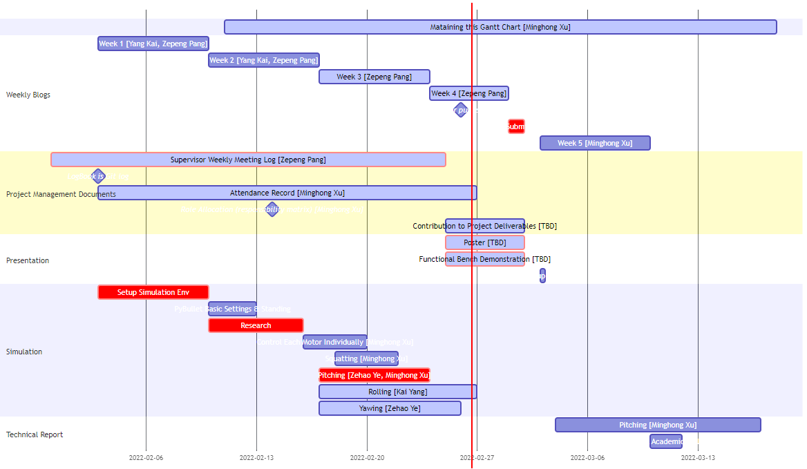
In a meeting with aa on Monday, aa set us a new task to make a gantt chart. The gantt chart makes the structure of our project clearer, and also allows members to collaborate with each other and allocate time more easily. Also our main task this week is to select the model we want to simulate and import the quadruped robot model file into pybullet. Learn how to use pybullet to simulate manipulating a robot. After the previous work is done, we plan everyone to try to write some simple code to make the robot move. For example, manipulating a joint of a robot and bending it.
Goals for week 2
- Select the quadruped robot model to use.
- Import the model into pybullet.
- Initially configure the simulation environment. e.g. gravity, simulated scenes, etc.
- Write simple code to move a joint and test.
Implementation of the task

There are three alternative models, called aliengo, laikago and a1. We studied the mobility of the joints of each model, the number of joints and other factors. These factors may affect our later simulations. We even considered copyright issues for the model. After comprehensive consideration, the third model in the figure, namely a1, was selected as the quadruped robot model to be used in our project. The model has a total of 12 movable joints. It can perform various actions very well. And its structure is relatively simple, it is very suitable for us beginners to get started. In addition, these three models are all models included in pybullet, which can be found in the data folder. This also saves us the step of querying the detailed data of the model.

The code in the figure is the basic operation code provided by pybullet. With these few lines of code, we set the gravity, floor, and simulation rate of the simulated environment. Through the last line of the code, we successfully imported the quadruped robot a1 into the simulation environment.

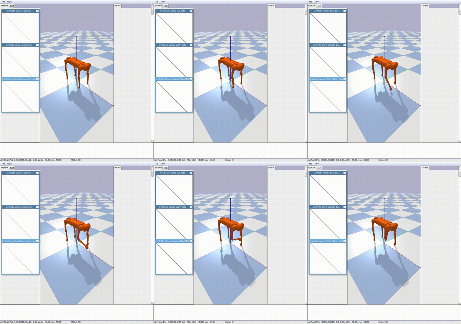
Through the code in the picture above, we control the robot’s joint number 4 to lift forward. The result of the code execution is shown in the video below. It can be seen that the robot’s right front leg is successfully raised forward.

After this, each member of the group actually tried it out. Everyone chooses different joints and different movement directions. The actual effect is similar to the video above, so we won’t show it again.

Following aa’s suggestion, we designed a gantt chart. From this chart, we can clearly see the assignment of tasks to each team member. The relationship between the various tasks is also clear at a glance. This undoubtedly makes it easier for us to control the progress of the project.
Week 2 summary
Learned read–eval–print loop (REPL), also termed an interactive toplevel or language shell, is a simple interactive computer programming environment that takes single user inputs,executes them, and returns the result to the user; a program written in a REPL environment is executed piecewise.
We completed the gantt chart task assigned by aa, which has a high positive significance for our work arrangement. Additionally, we selected a quadruped robot model for the simulation. Second, we configured the environment in the simulation software, such as gravity, floor, etc. In the end, the team members all succeeded in moving one of the robot’s joints. This was a successful start for us, with a theoretical understanding of how to manipulate the joints to accomplish the simulated motion. Because an action is completed by the simultaneous motion of multiple joints, what we need to do next is to analyze how to call multiple joints at the same time to complete the simulation of the action.